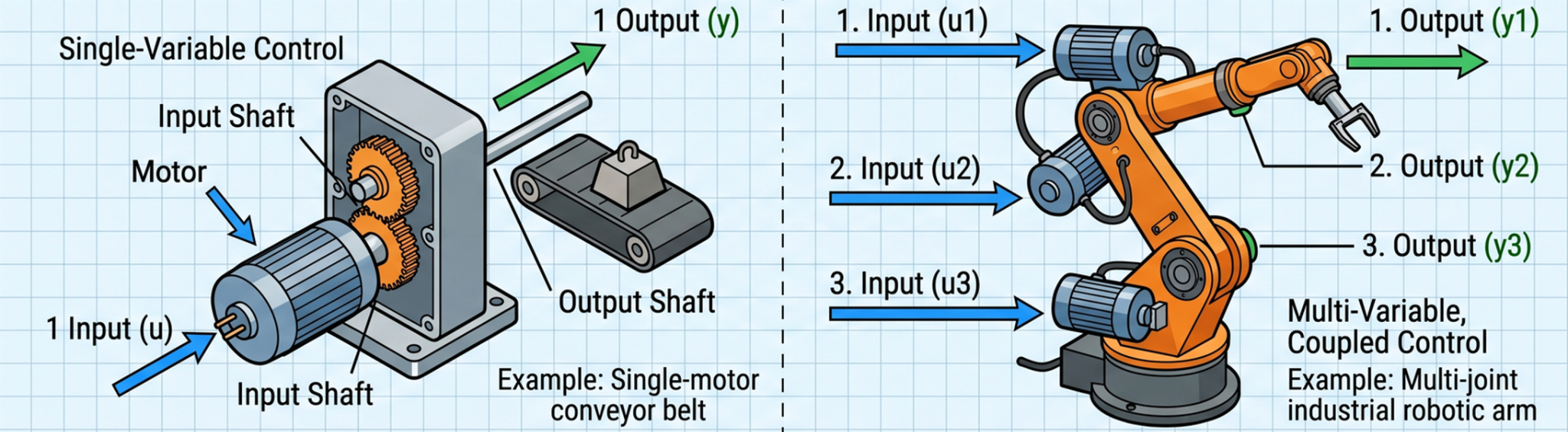
In the evolution of a control systems engineer, there is a definitive moment when classical PID (Proportional-Integral-Derivative) control reaches its physical and mathematical limits. While PID is the workhorse of industrial automation, complex multi-input multi-output (MIMO) systems—such as muti-DoF robots , aerospace vehicles, and the Acrome 3-DoF Copter—require a more sophisticated approach.
To achieve optimal performance, minimize energy consumption, and handle stochastic noise, engineers must transition to modern control theory. This article explores the design and implementation of advanced control experiments, moving from the deterministic world of Linear Quadratic Regulators (LQR) to the stochastic robustness of Linear Quadratic Gaussian (LQG) control, and finally into the challenging domain of nonlinear control strategies.
Why Move Beyond PID?
The 3-DoF (Degrees of Freedom) helicopter system is a classic benchmark in control labs precisely because it exposes the weaknesses of simple controllers. It is inherently: 1. Nonlinear: The aerodynamic forces produced by the rotors do not scale linearly with motor voltage. 2. Highly Coupled: Changing the pitch of the main rotor creates a reaction torque that directly impacts the yaw axis. 3. Unstable: Without active control, the system will not maintain a steady pose.
While you can “decouple” these axes and tune two independent PID loops, this approach ignores the underlying physics of the system. Advanced control techniques, however, treat the system as a unified whole, using a mathematical model to predict and compensate for these interactions in real-time.
Linear Quadratic Regulator (LQR): Optimal Deterministic Control
The LQR control experiment is often the first step into modern control. Unlike PID, which focuses on error correction, LQR is an optimal control strategy. It seeks to find a control law that minimizes a specific cost function (J), balancing the speed of error elimination against the amount of energy (control effort) expended.
The Mathematical Framework
For a system represented in state-space form (x'=Ax+Bu), the LQR controller minimizes:
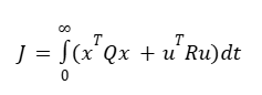
Where: * Q is the state-weighting matrix (how much you care about position/velocity errors). * R is the control-weighting matrix (how much you care about motor power usage).
The resulting control law is a simple state-feedback gain matrix K:
u=−Kx
MATLAB Implementation
Calculating the LQR gain (ie. K) matrix for a 3-DoF platform is quite simple and efficient in MATLAB™:
% LQR Gain Calculation for 3-DoF Copter
% Values are randomly selected  for representation purpose

% Define linearized A and B matrices (obtained via system identification)
A = [0 1 0 0; -0.5 -0.1 0 0; 0 0 0 1; 0 0 -0.8 -0.2];
B = [0 0; 1.2 0.1; 0 0; 0.1 1.5];

% Define Weighting Matrices
Q = diag([100, 10, 100, 10]);

% High weight on pitch/yaw position
% Low weight on control effort
R = diag([0.1, 0.1]);

% Compute Optimal Gain Matrix
KK = lqr(A, B, Q, R);
disp('Optimal LQR Gain Matrix K:');
disp(K);
Please note that the “lqr” command is part of the Control System Toolbox® of the Matlab software.
Linear Quadratic Gaussian (LQG): Handling Noise and Hidden States
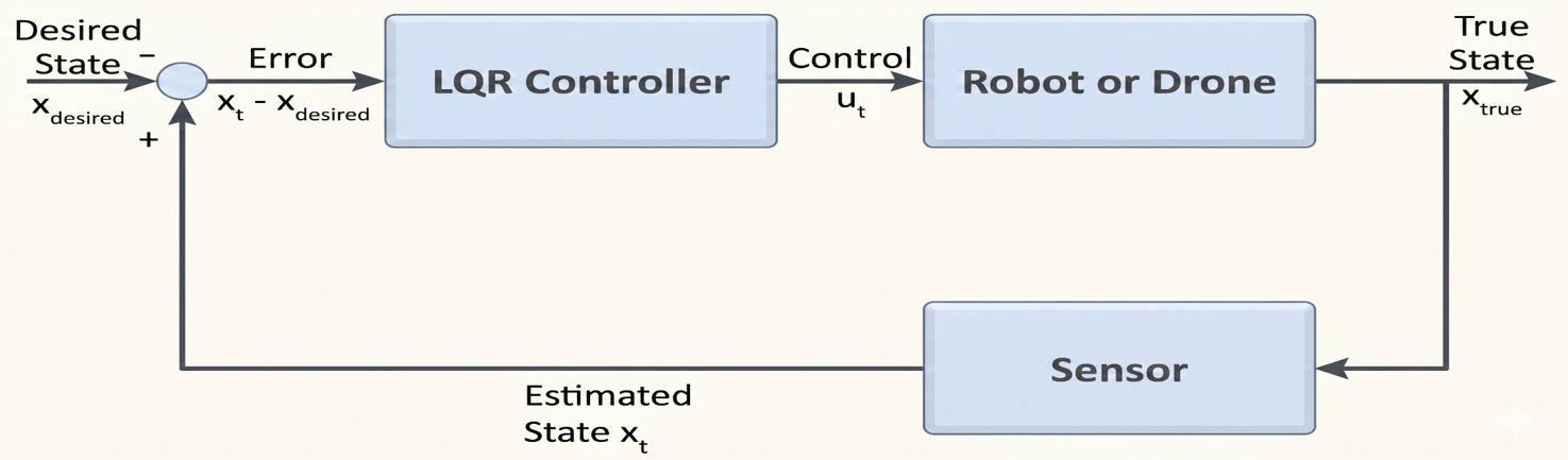
In a real laboratory, we rarely have perfect information. Sensors have noise, and some states (like angular velocities) might not be directly measured. This is where the LQG control tutorial becomes essential.
LQG is the combination of an LQR controller and a Kalman Filter. The Kalman Filter acts as an optimal observer, estimating the true state of the system by fusing noisy sensor data with the mathematical model.
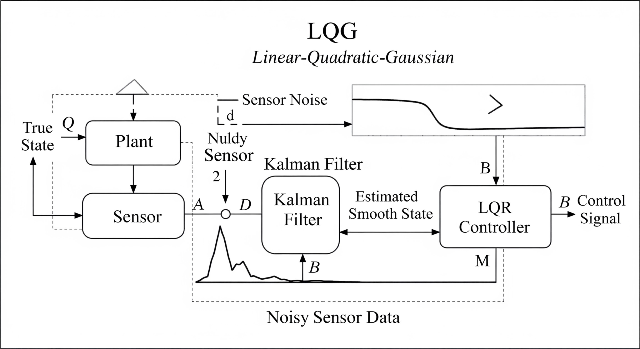
The Kalman Filter Experiment
A Kalman filter operates in two steps: 1. Predict: Use the model to estimate where the 3-DoF platform should be in the next millisecond. 2. Update: Use the noisy sensor data (encoders/IMU) to correct that prediction.
The “LQG” strategy ensures that even if your pitch sensor is jittery, the controller receives a smooth, estimated state, preventing the motors from vibrating and reducing mechanical wear.
Acrome’s 3-DoF Copter has a modular I/O module as well, which is used to measure and model the inherent noise of the encoders as well as the IMU sensor. This is a very handy tool and simplifies the LQG design experiment.
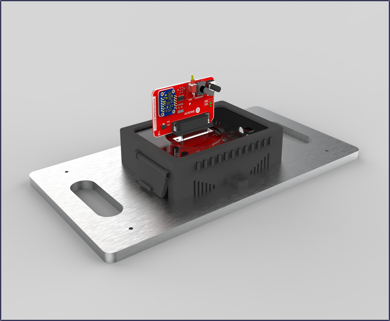
3-DoF Copter’e modular I/O test module is connected to the main controller. Simple data acquisition and modelling tasks can be performed in a repeatable manner
Nonlinear Control: Embracing the Real World
While LQR and LQG are powerful, they rely on a linearized model (usually around the hover point). If the 3-DoF Copter performs large-angle maneuvers, the linear model fails. This necessitates a nonlinear control experiment.
Common nonlinear strategies for twin-rotor systems include: * Sliding Mode Control (SMC): Extremely robust against model uncertainties and external disturbances (like wind). * Feedback Linearization: Mathematically “canceling out” the nonlinearities of the system to make it behave like a linear one. * Backstepping: A recursive design method that is particularly effective for underactuated systems.
Step-by-Step Experiment Workflow
To run these advanced control experiments on a platform like the Acrome 3-DoF Copter, follow this standardized workflow:
- System Identification: Perform experiments to determine the A and B matrices of your hardware.
- Controller Design (MATLAB): Use the lqr or lqg commands to calculate your gains based on desired performance.
- Stability Analysis: Check the eigenvalues of the closed-loop system (A−BK) to ensure they are in the left-half plane.
- Simulink Simulation: Run a high-fidelity simulation to verify that the controller handles coupling and saturation limits.
- Real-Time Execution: Deploy the code to the hardware. Start with low gains and gradually increase Q weights.
- Data Analysis: Export the real-time telemetry to compare the “Commanded vs. Actual” response.
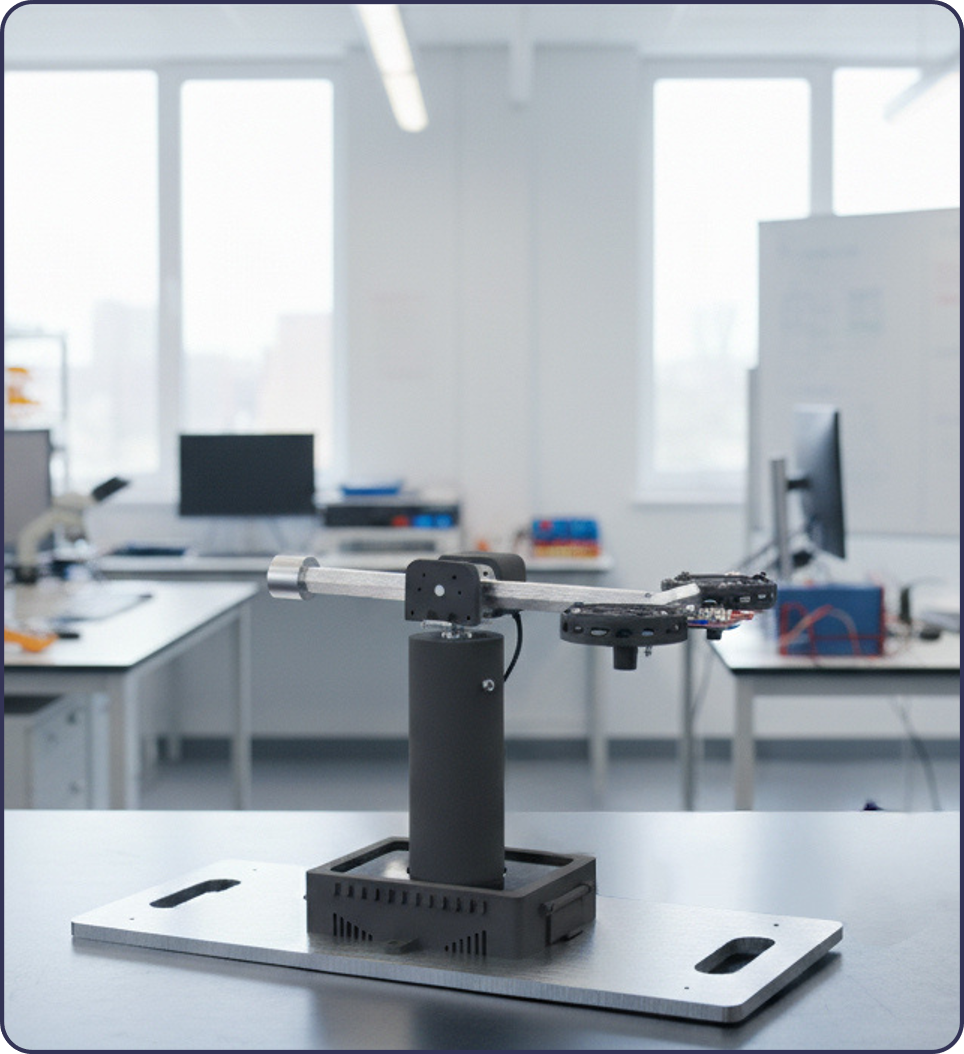
Advanced Control on the Acrome 3-DoF Copter
The Acrome 3-DoF Copter is specifically designed for these advanced transitions. It provides the high-resolution feedback and deterministic communication required for LQG and nonlinear control.
How the Platform Enables Advanced Research
- Open Architecture: Unlike “black-box” drones, the 3-DoF Copter allows full access to the control loops in MATLAB/Simulink.
- Built-in Estimators: The system includes pre-configured Kalman filter templates, allowing students to focus on the Kalman filter experiment logic rather than low-level driver code.
- Nonlinear Validation: The platform’s wide range of motion (esp. unlimited yaw) provides the perfect testbed for validating nonlinear control experiment strategies across different operating points.
Want to run these experiments on real hardware? Explore the 3-DoF Copter — Acrome’s lab-ready twin rotor platform designed for everything from basic PID to advanced LQG and nonlinear control research.
Conclusion
Moving from PID to advanced control techniques like LQR, LQG, and nonlinear strategies is a significant leap in engineering capability. It allows for the control of systems that are faster, more efficient, and more robust. By utilizing a high-fidelity experimental platform like the Acrome 3-DoF Copter, researchers and students can bridge the gap between abstract mathematical theory and the tangible reality of physical motion.
Frequently Asked Questions (FAQ)
1. Is LQR always better than PID? Not necessarily. PID is easier to implement and requires no mathematical model. LQR is “better” in the sense that it is mathematically optimal, but it requires an accurate state-space model of the system to function correctly.
2. Why do I need a Kalman Filter for LQG? In most 3-DoF platforms, you measure angles (position) but not angular rates (velocity). The Kalman Filter estimates these velocities from the position data while simultaneously filtering out sensor noise.
3. What happens if my nonlinear model is slightly wrong? This is where Robust Control (like Sliding Mode Control) shines. These controllers are designed with a “safety margin” to handle model inaccuracies or changing environmental conditions (like a dying battery or worn-out propellers).
4. Can I run these experiments in real-time? Yes. Modern microcontrollers and PC-based controllers (like those used in the Acrome system) are more than fast enough to solve these matrix equations at 1kHz or higher, which is necessary for stable flight control.
5. How do I choose the Q and R matrices in LQR? This is often an iterative process known as “Bryson’s Rule.” Generally, you start with identity matrices and increase the values in Q for the states you want to settle faster, and increase R if you want to reduce motor vibration or power consumption.
Deep Dive: The Kalman Filter in Practice
The Kalman filter experiment is perhaps the most transformative part of the LQG workflow. In a 3-DoF helicopter, the sensors (encoders for pitch, yaw, and travel) provide raw data that is inherently “stepped” or “quantized.” If you were to simply differentiate this position data to find the velocity, the resulting signal would be incredibly noisy, causing the motors to “chatter.”
The Kalman filter solves this by maintaining a “belief” about the state of the system. It uses the physical model (the A and B matrices) to project the state forward in time (the Prediction Phase). When the new sensor reading arrives, it calculates the Kalman Gain, which determines how much to trust the model versus how much to trust the sensor (the Update Phase).
For advanced researchers, tuning the Kalman filter’s process noise covariance (Qk) and measurement noise covariance (Rk) is a critical skill. A high Rk tells the filter that the sensor is very noisy, causing it to rely more on the model—this results in a smoother but potentially “laggy” estimate. Conversely, a low Rk makes the filter highly responsive to sensor changes but more susceptible to noise.
Solving the Coupling Problem with MIMO Control
One of the primary reasons to use state feedback control lab techniques like LQR is to address the “coupling” between the main and tail rotors. In a 3-DoF Copter, the main rotor provides lift (pitch), but its rotation also creates a torque that wants to spin the body (yaw).
In a classical PID setup, the yaw controller has to “fight” the disturbances created by the pitch controller. In an LQR or LQG setup, the controller “knows” about this relationship because it is encoded in the off-diagonal terms of the B matrix. When the LQR controller decides to increase the pitch, it simultaneously adjusts the yaw rotor to compensate for the anticipated torque. This results in a system that appears much more stable and “intelligent” than a decoupled PID system.
Practical Implementation: From Simulink to Hardware
For many students and engineers, the MATLAB Simulink control experiment is the bridge to reality. Simulink provides a visual environment where the state-space equations, LQR gains, and Kalman filters can be connected as blocks.
The typical implementation pipeline on the Acrome platform involves: 1. Block-Based Design: Dragging the LQR gain block and connecting it to the state-feedback loop. 2. Saturation Handling: Adding “Anti-Windup” or saturation blocks to ensure the controller doesn’t ask for more voltage than the motors can physically provide. 3. Real-Time C-Code Generation: Using Simulink Coder to convert the visual model into high-performance C code that runs directly on the platform’s processor. 4. Hardware-in-the-Loop (HIL) Testing: Running the controller against a simulated copter model while it is connected to the real interface, ensuring that the timing and communication are perfect before the first “flight.”
The Future: Reinforcement Learning and Adaptive Control
While this guide focuses on LQR, LQG, and established nonlinear methods, the field of advanced control experiments is rapidly moving toward data-driven approaches.
Adaptive Control allows the system to change its own gains in real-time as the hardware ages or as environmental conditions change (e.g., a propeller getting slightly damaged). Reinforcement Learning (RL), a subset of AI, allows a controller to “learn” the optimal policy through trial and error in a simulation, often discovering control strategies that are even more efficient than human-designed LQR gains.
The Acrome 3-DoF Copter is an ideal platform for these cutting-edge experiments, as its high-speed data logging and open-source API allow researchers to easily feed real-world data into their machine learning models.
Final Thoughts for the Lab Coordinator
When setting up an advanced control systems lab, the choice of hardware is as important as the curriculum. A platform must be robust enough to survive the inevitable “unstable” controller designs that students will produce, yet sensitive enough to show the subtle differences between an LQR and an LQG implementation.
By guiding students through the progression from PID to LQR, then adding the Kalman Filter for LQG, and finally exploring Nonlinear or Adaptive strategies, you are providing them with a complete toolkit for modern engineering. They leave the lab not just knowing how to “turn a knob” to tune a system, but how to mathematically optimize a complex machine for the real world.
Summary of Key Takeaways
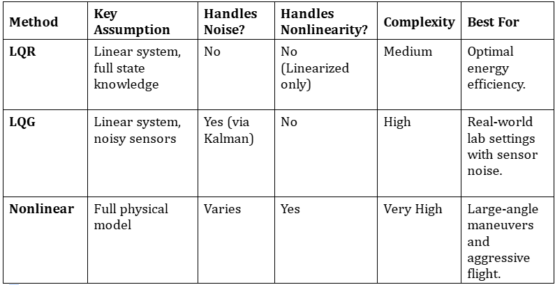
- LQR provides optimal control but requires a clean, linear environment.
- LQG is the gold standard for real-world linear systems, combining LQR with a Kalman Filter to handle noise.
- Nonlinear Control is necessary for systems operating far from their equilibrium points.
- System Identification is the mandatory first step for any model-based control strategy.
- Hardware Validation on platforms like the Acrome 3-DoF Copter is essential to prove that theoretical models hold up in the physical world.
Author
