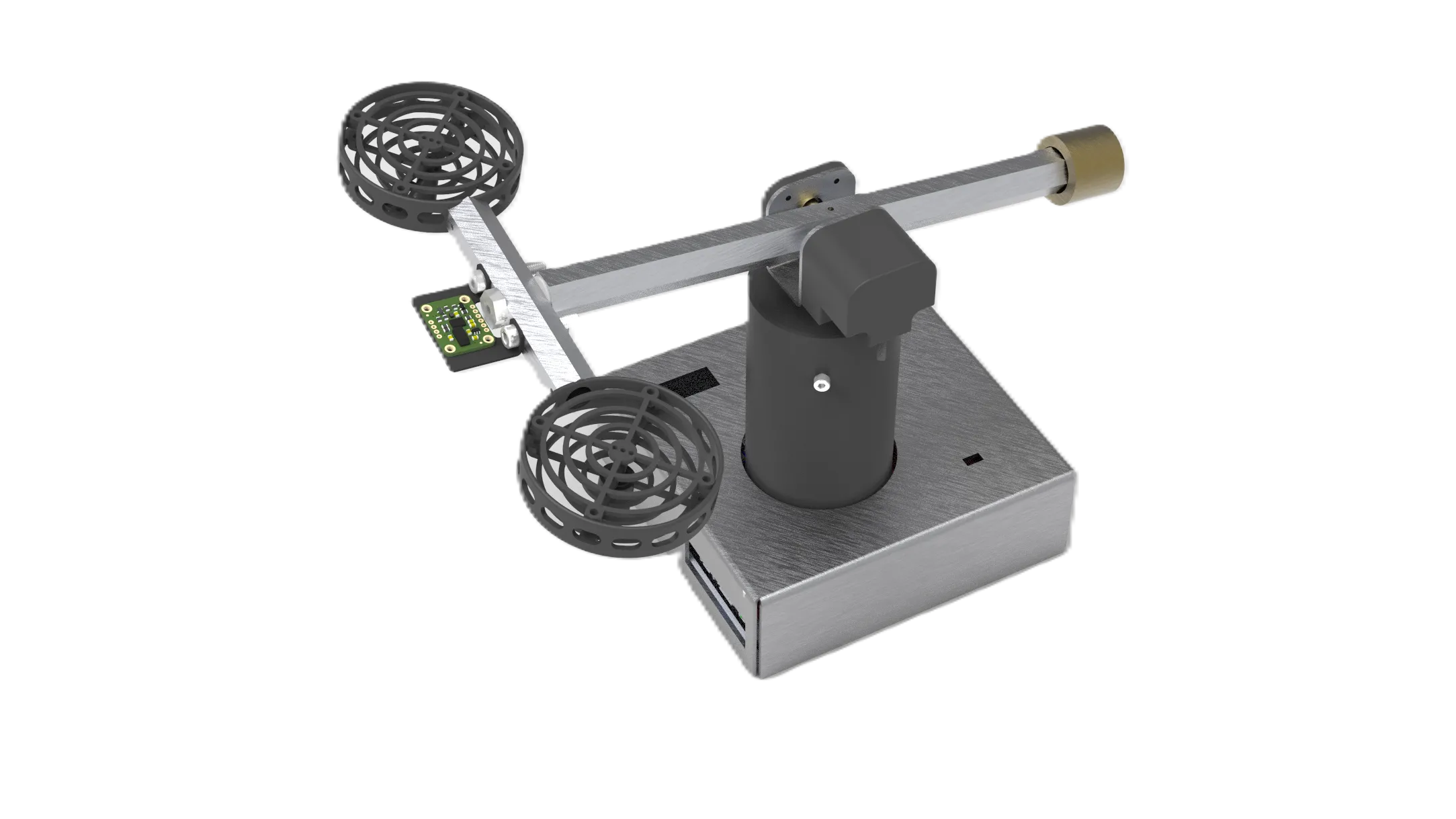
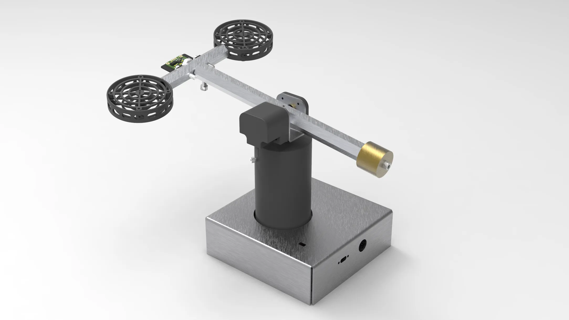
Thank you! Your request is received and we will contact you shortly for the requested file/information.
Oops! Something went wrong while submitting the form.
Product Media
REFERENCE CUSTOMERS
OVERVIEW
The ACROME 3-DoF Copter is a versatile educational platform that allows students to explore the principles of flight dynamics and MIMO control systems. Thanks to its modular design, digital-twin simulation files and open-source examples, it is perfect for both undergraduate education and reserach use. The 3-DoF copter comes with a comprehensive curriculum that includes theoretical concepts and practical applications, enabling learners to gain a deep understanding of aerodynamics and MIMO control structures. The modular boards allow low-level hands-on experiences and HIL simulations as well.
X and Y Axis +/-60 mm Z Axis +/-50 mm Roll, Pitch, Yaw +/- 20°
Up to +/-300 mm Up to +/-150 mm Up to +/- 45°
Position Repeatability
+/- 100 µm
Down to +/- 25 µm
Angular Sensitivity
0.2°
Down to 0.1°
Max. Linear Speed
40 mm/sec.
Up to 80 mm/sec.
Height (min-max)
402-502 mm
330-920 mm
Platform Diameter
350 mm (hexagonal)
250-1000+ mm
Base Diameter
450 mm (hexagonal)
450-1000+ mm
Weight
14 kgs (31 lbs)
Based on custom options
SPECIFICATIONS
Payload
Workspace
± 30° in Pitch, ± 30° in Roll, ± 180° in Yaw (unlimited)
Position Repeatability
Angular Sensitivity
Max. Speed
180° / second
Height (min-max)
263 mm. - 352 mm. (± 2mm.)
Height
Rod Height
Platform Dimensions (Length * Width)
Base Dimensions (Length * Width)
510mm. x 146mm. (± 2mm.)
Weight
2500 gr. (base unit only)
Propeller Wingspan
55 mm. (± 0.5mm.)
Ball Diameter
Magnet Diameter
Rod's Diameter
Motor Type
Brushed DC motor
Feedback Sensors
Encoder, IMU
Power Requirement
12V - 5A
FEATURES
Solid body for precise motion and measurement
Getting Started Program with rich Graphical User Interface for out-of-the-box user experience
High resolution incremental encoder for angle measurement of rotor arm
Modular I/O boards for learning the sensors and testing the thrust of the motors
Assembled and ready to control plant with the integrated power unit
Implementation of advanced digital control techniques
Fully compatible with MATLAB®/Simulink®
Fully documented system models and parameters provided for MATLAB®/Simulink® and Simscape
Enables students to create their own real-time algorithms
Open architecture with extensive courseware, suitable for undergraduate coursesand advanced control research topics
FAQs
What is 3-DoF Copter
The 3-DoF Copter is an automatic control system, used for teaching MIMO control systems and various related control algorithms.
What is a 3-DoF Copter used for?
The 3-DoF Copter is used for learning and trying advanced algorithms to control the 3 different angles of the product via changing the thrust of its dual propellors.
What are the feedback sensors available?
Two encoders are used to determine the pitch and yaw angle of the moving arm, where the 3rd angle (roll) is calculated in the software. An additional Inertial Measurement (IMU) sensor is also used to directly measure all 3 angles of its arm.
What controller types can I use to control the product?
A getting started example based on LQR is provided. You can also lock the product to move in 1 angle (pitch) and use simpler P/PI/PID algorithms for 1-DoF position control. Advanced controller algorithms such as estimators, LGQ, reinforcement learning can also be developed and used.
Does the product comes with a controller and software/courseware?
Product comes with the controller, software and a companion courseware with example source codes.
Is there any after-sales support or training for the product?
A complimentary online support session is available after the delivery of the products. Standard support is provided via the phone, e-mail or remote desktop connection.
CURRICULUM
COMPONENTS OF 3-DOF COPTER
Base Unit and Electronics
Copter Tower (modular)
Sensor Simulation Add-On Board
Thrust Measurement Add-On Board
FEEDBACK STRUCTURES
Calculating Angle from Encoders
Basics of Filtering
Getting Angle from IMU Sensor
SYSTEM MODELING
What is coupled dynamics?
Introducing the 3-DoF axes
Modeling of 3-DoF Helicopter
Electronics Structure
Using Sensor Board
Using Thruster Board
CONTROL SYSTEM DESIGN
Introduction to Controllers
PID for 1-DoF Control
LQR Basics
PERFORMANCE MEASURES
Time Domain Characteristics
Steady State Response and Error
Comparing Simulation Results
ADD-ON BOARD EXPERIMENTS
Measuring Thrust with Loadcell
Filtering Loadcell Measurements
Hardware In the Loop Simulation
Info Sheet Download
Thank you! Your request is received and we will contact you shortly for the requested file/information.
Oops! Something went wrong while submitting the form.
SPECIFICATIONS
*We offer customization in our product upon customer’s request.
RELATED ARTICLES
Twin Rotor MIMO Control System Modeling, Dynamics, and Experiment Design
10
Min
The twin rotor system is a classic, dynamically coupled Multi-Input Multi-Output (MIMO) platform, often used as a laboratory model to explore complex control principles like those found in a helicopter. The primary challenge is the dynamic cross-coupling between the two inputs (rotor thrusts) and two outputs (pitch and yaw angles). Designing a robust controller requires accurate mathematical modeling, typically using a state-space representation to capture the system's internal states holistically.
Access Acrome Lab Solutions Remotely to Achieve Your Distance Learning Goals
With the Remote Lab, experience the new way of laboratory studies. Run your algorithms on real hardware from anywhere and anytime without a compromise on accuracy.