Introduction
Picture a chrome ball rolling along a tilting beam, or a pendulum fighting gravity to stay upright. To the casual observer, these look like science fair projects or desktop curiosities.
But to a Design Engineer, these platforms represent the front line of control theory.
There is a misconception that these systems are just educational tools. In reality, they are sophisticated proxies for the most difficult non-linear control problems in modern manufacturing. The physics governing that rolling ball are mathematically identical to those governing fluid handling in high-speed bottling lines. The instability of that pendulum mirrors the challenges of vertical stabilization in rocketry and anti-sway algorithms in gantry cranes.
The transition from a benchtop prototype to a production machine is not just about scaling up size; it is about scaling up complexity. It requires bridging the gap between the perfect theoretical models of the simulation and the friction, resonance, and noise of the factory floor.
The Ball & Beam: Mastering Sensor Noise and Derivative Gain
The Ball & Beam setup—a classic experiment featured in platforms like the Acrome's Ball Beam Experiment system — presents a deceptively simple goal: maintain the position of a rolling ball on a tilting beam.
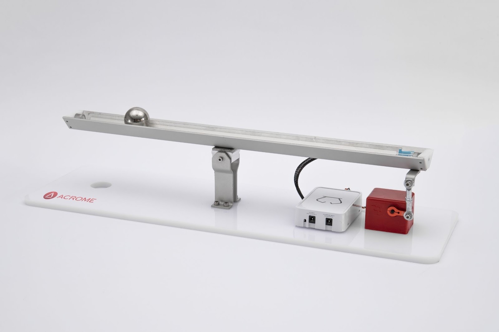
In a textbook simulation, this is a standard PID loop. You measure error (position), apply a proportional correction, and dampen the oscillation. However, in the real world, the Ball & Beam highlights a critical industrial challenge: Derivative Noise Amplification.
To stabilize the ball without overshoot, the control loop requires a strong Derivative (D) term to predict future error. However, real-world position sensors are never perfect. They contain noise. Since the Derivative term calculates the rate of change of the error, high-frequency sensor noise is amplified exponentially, causing the servo motor to jitter or overheat.
This is the exact scenario engineers face in web handling and tension control systems. Just as the ball rolls freely, the web material is compliant. If the servo drive cannot filter out sensor noise while maintaining a high current loop bandwidth, the material tears. The prototype teaches the engineer not just how to tune P, I, and D, but how to implement low-pass filters and feed-forward gains to maintain stability without sacrificing response time.
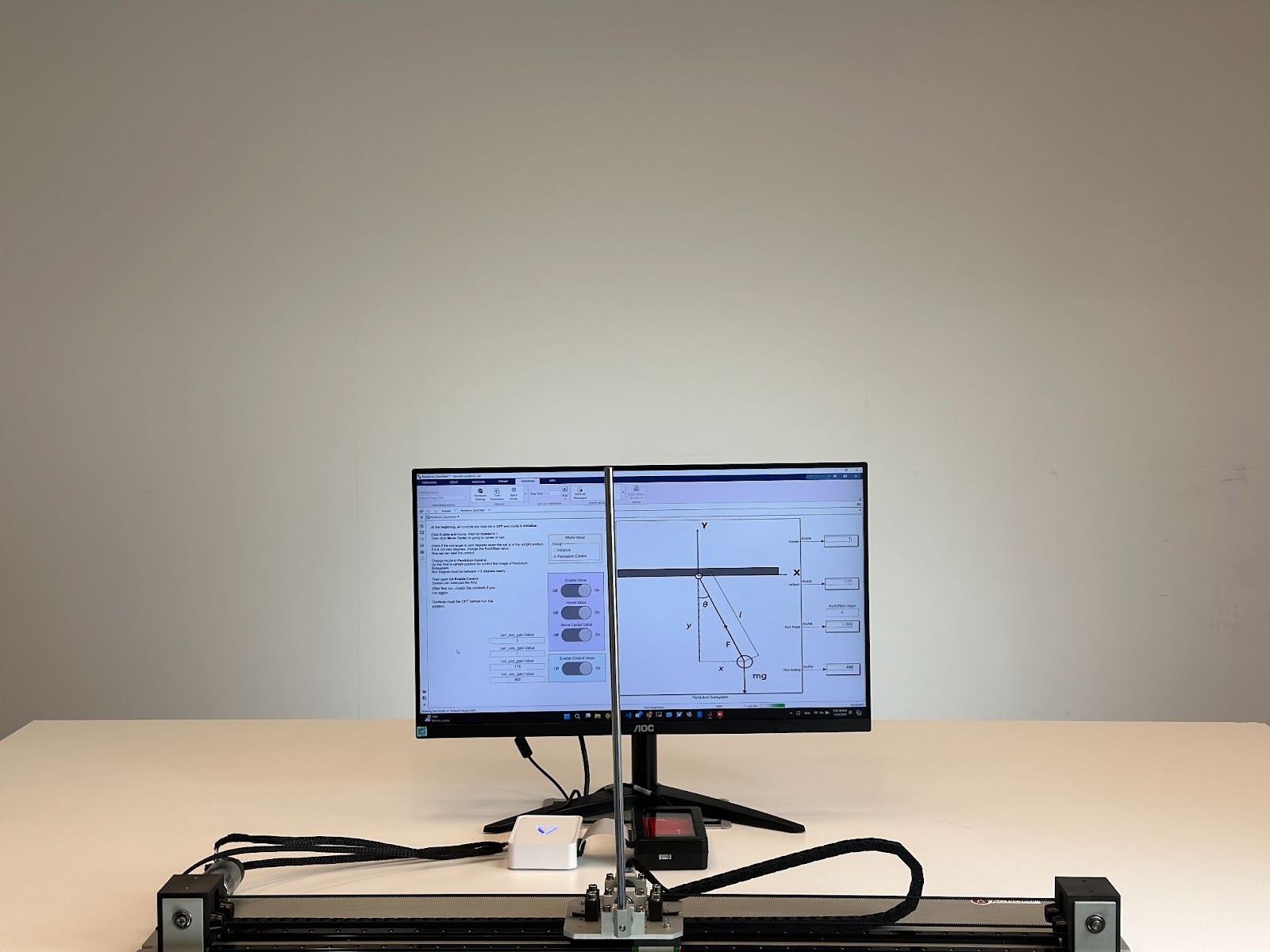
The Inverted Pendulum: Stabilizing Unstable Equilibriums
The Inverted Pendulum (and its multi-degree-of-freedom variants like the Acrome's Linear Inverted Pendulum) represents a system in "unstable equilibrium." Unlike a standard motion axis that naturally stops when power is cut, an inverted pendulum fails catastrophically if the control loop lags by even a few milliseconds.
This setup forces the engineer to confront Latency and Bandwidth.
In a simulation, the controller’s command is executed instantly. In reality, there is a delay between the motion controller calculating a trajectory and the servo drive executing the current command. If the total system latency exceeds the mechanical time constant of the pendulum, the system becomes uncontrollable.
This dynamic is directly applicable to:
- AGVs (Automated Guided Vehicles): Specifically those carrying high-center-of-gravity loads where rapid acceleration can cause tipping.
- Gantry Cranes: Where "anti-sway" logic is essentially an inverted pendulum equation reversed.
- Bipedal Robotics: Where the "Zero Moment Point" must be dynamically adjusted to prevent falling.
Success in these applications relies on the servo drive. The drive must possess a high switching frequency and a fast current loop update rate to react to disturbances before gravity takes over.
The "Dirty" Reality of Industrial Environments
The primary difference between the lab and the factory is "noise"—both electrical and mechanical.
Lab prototypes are typically pristine. Friction is consistent; loads are balanced. Real machines deal with stiction, backlash, and varying loads. When scaling a control strategy from a prototype to a production machine (e.g., using AMC servo drives in a CNC application), the engineer must account for:
- Thermal Derating: A prototype runs for 10 minutes; a factory machine runs 24/7.
- Inductance Mismatch: Real motors in the field often have different inductance values than the lab motors, requiring drives that can automatically tune current loops to match the motor impedance.
- EMI/RFI: Industrial environments are electrically noisy. A control scheme that works on a shielded lab bench may fail when placed next to a 480V welding robot.
The Role of High-Performance Hardware
The "brain" of the operation (the algorithm developed in MATLAB or Simulink) is only as good as the "muscle" (the servo drive) executing the move.
The transition from a concept on an Acrome platform to a deployed machine often fails because the industrial hardware cannot match the theoretical response times of the lab simulation. This is where high-performance servo drives, such as those from ADVANCED Motion Controls, become the linchpin of the design.

By utilizing drives with high bandwidth and localized intelligence, engineers can offload processing from the main controller. Features like "Safe Torque Off" (STO) and hardware-based limit integration allow the drive to protect the mechanics even if the high-level software crashes.
Conclusion
"From Prototypes to Production" is a discipline of verification. By treating platforms like the Ball & Beam not as toys, but as stress-tests for control algorithms, engineers can identify the limits of their logic before cutting metal.
When these verified algorithms are paired with industrial-grade servo drives capable of handling the noise, heat, and latency of the real world, the result is a machine that doesn't just work in theory—it performs in practice.
Author