The global telecommunications landscape is undergoing a monumental shift with the deployment of massive Low Earth Orbit (LEO) satellite constellations. Unlike traditional geostationary (GEO) satellites that remain fixed in the sky, LEO satellites are in constant, rapid motion, orbiting the Earth at velocities exceeding 7.5 km/s. For ground station antennas (GSAs) to maintain a stable link with these fast-moving targets, they must possess extraordinary tracking speed and precision. Validating these antennas in a laboratory environment requires more than just signal simulation; it requires high-fidelity physical motion simulation using 6-Degree-of-Freedom (6-DoF) platforms. However, achieving a “virtual space” in the lab is a complex engineering feat that must account for terrestrial limitations like gravity and atmospheric pressure. This article explores the advanced strategies for testing LEO ground station antennas under motion, addressing critical technical nuances from Doppler compensation to the limitations of parallel robotics.
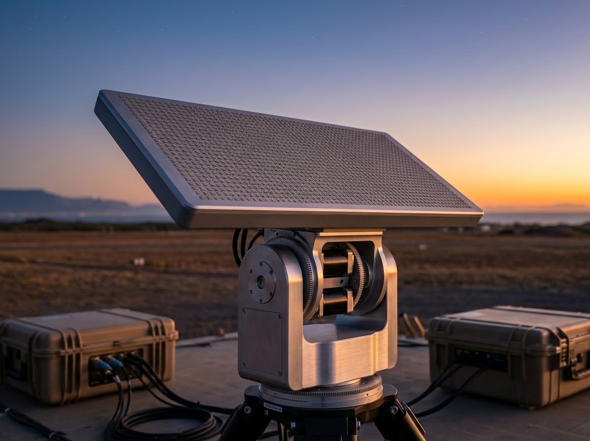
The Tracking Challenge of LEO Ground Segments
The primary difference between LEO and GEO communication lies in the tracking dynamics. A LEO satellite passes from horizon to horizon in a matter of minutes. During this window, the ground station antenna must accurately point its beam toward the satellite, compensating for the satellite’s high angular velocity and the resulting signal distortions.
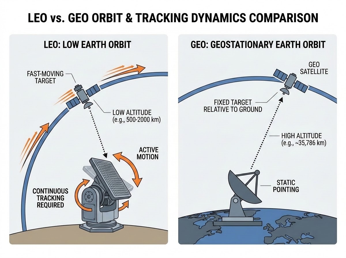
1. High-Speed Signal Dynamics
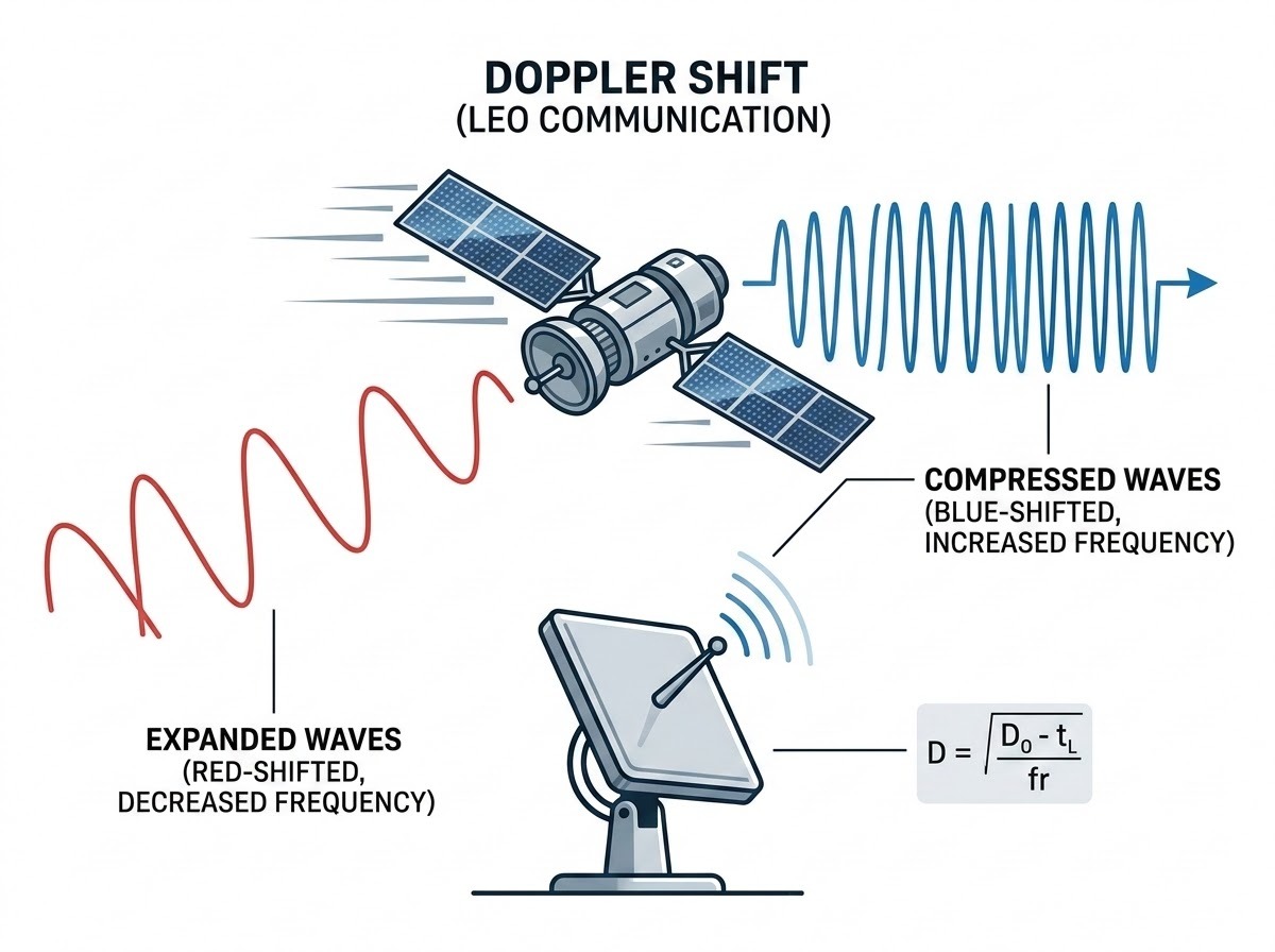
As the satellite moves relative to the ground station, the communication frequency experiences a significant Doppler shift. If the antenna’s tracking system and the receiver’s signal processing units cannot handle this shift, the link will be lost.
Technical Correction: The Doppler Formula The Doppler shift (fd) is a function of the carrier frequency (fc), the relative velocity between the transmitter and receiver (vr), and the speed of light (c): fd=fc.vr.c
In LEO applications, where vr can be several kilometers per second, accurate Doppler compensation is the first line of defense for a stable connection.
2. Mechanical Precision and Latency
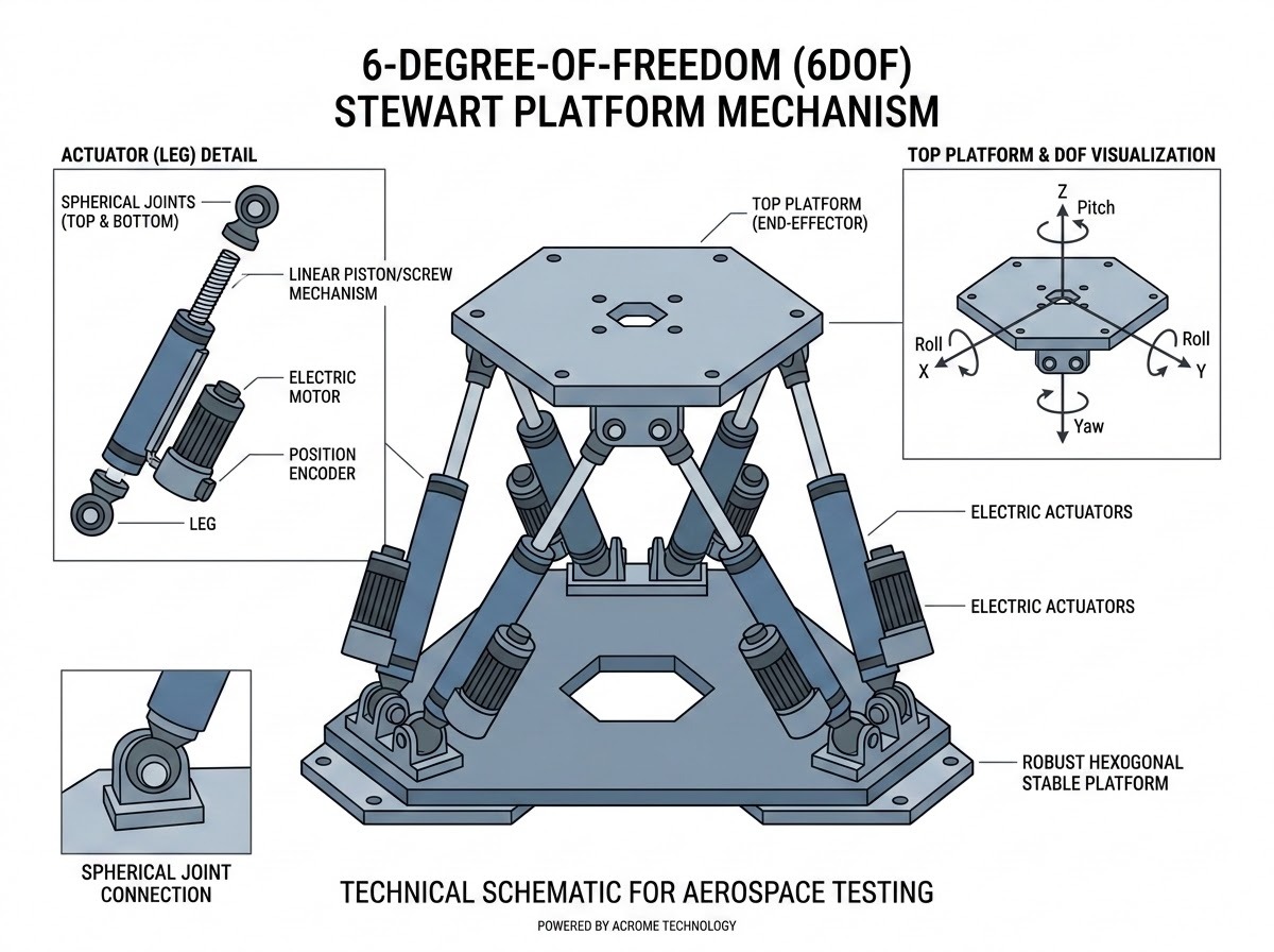
Tracking a LEO satellite requires the antenna to move with high angular acceleration. Any mechanical latency or “jitter” in the antenna’s positioning system can result in pointing errors. In the lab, engineers use 6-DoF Stewart Platforms to mount these antennas and simulate the exact tracking trajectories they will follow in the field. This allows for the validation of the antenna’s servo-control loops and structural integrity under dynamic stress.
The Role of 6-DoF Stewart Platforms in Antenna R&D
Stewart Platforms, or hexapods, are parallel robots that offer six degrees of freedom: three translational (X, Y, Z) and three rotational (Roll, Pitch, Yaw). Their high dynamic motion and precision make them ideal for replicating the disturbances the LEO antennas suffice on daily usage scenarios.
Hardware-in-the-Loop (HIL) Architecture for Antenna Testing
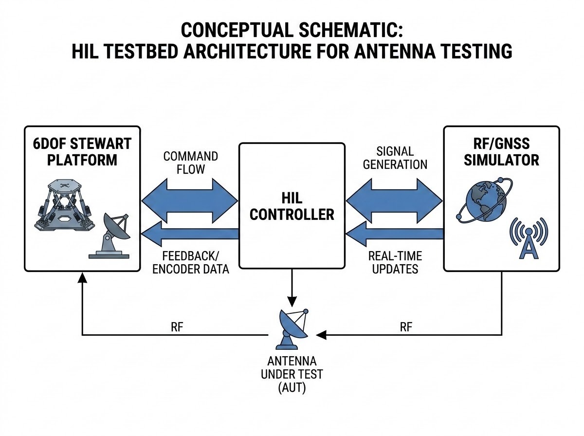
A modern HIL testbed for LEO antennas integrates mechanical motion, RF signal generation, and real-time control.
Real-Time Synchronization
The “brain” of the testbed calculates the relative position of the LEO satellite and the ground station. It then sends commands to:
- The Stewart Platform: To physically move the antenna through the tracking trajectory.
- The RF/GNSS Simulator: To generate the signal with the correct Doppler shift, phase, and atmospheric delay.
The synchronization between these two systems must be sub-millisecond. If the antenna moves but the signal simulator doesn’t update the phase accordingly, the receiver will experience a “signal-motion mismatch,” leading to artificial tracking failures.
The Role of Parallel Robotics in Ground Segment Innovation
Parallel robots, particularly the 6-DoF motion bases developed by specialists like Acrome, are essential for the R&D of next-generation phased array and parabolic tracking antennas. Their ability to handle high payloads while maintaining micron-level precision allows engineers to push the boundaries of what is possible in LEO communications.
Acrome’s expertise in motion control directly supports this aerospace vertical by providing the mechanical foundation for these complex HIL simulations. By acknowledging and addressing the terrestrial limitations of these platforms—such as gravity interference and workspace constraints—Acrome enables researchers to build more accurate, reliable, and effective tracking systems.
Conclusion
Testing LEO ground station antennas is a sophisticated balancing act between mechanical dynamics and RF signal processing. While 6-DoF Stewart Platforms are the industry standard for high-precision tracking simulation, they are not a “magic bullet.” A technically sound testing strategy must account for the limited workspace of parallel robots, the interference of Earth’s gravity on inertial sensors, and the environmental constraints of TVAC chambers. By integrating gravity compensation algorithms and hybrid motion architectures, R&D teams can move closer to a true “virtual space” validation, ensuring that our global satellite networks remain connected, no matter how fast they move.
Hybrid Testing Architectures: Stewart Platforms and Gimbals
To address the workspace limitations of parallel robots, the industry has moved toward hybrid testing architectures. These systems combine the strengths of different robotic geometries to create a more comprehensive simulation environment. In this setup, a high-precision 6-DoF Stewart Platform acts as the “Base Motion Simulator.” It replicates the high-frequency vibrations, structural jitter, and small-scale translational shifts that a ground station might experience (e.g., due to wind loading or nearby industrial activity).
On top of this platform, a 2-axis or 3-axis motorized gimbal is mounted. The gimbal provides the wide-angle, continuous rotational freedom needed to track a LEO satellite from horizon to horizon.
Why this matters: This configuration allows engineers to test the “Pointing Accuracy” of the antenna while it is simultaneously subjected to high-frequency mechanical disturbances. It validates the antenna’s ability to maintain a narrow beamwidth connection even when the ground station itself is not perfectly stable.
Air-Bearing Platforms for Frictionless Simulation
For certain specialized tests, particularly those involving the validation of momentum wheels or reaction control systems within an antenna’s orientation unit, air-bearing platforms are used. These platforms use a thin film of compressed air to create a near-frictionless environment. - The Limitation: While air bearings allow for smooth, unrestricted rotation, they lack the “active” dynamic control of a Stewart Platform. They cannot easily replicate a specific, high-acceleration tracking trajectory. Therefore, they are often used in the earlier stages of R&D for “passive” stability testing, while Stewart Platforms are used for “active” tracking validation.
The Economics of Laboratory Validation
Beyond the technical necessity, there is a clear economic argument for motion-based laboratory testing. The cost of a failed LEO mission, or even a poorly performing ground segment, can run into the millions.
1. Reducing the “Time to Market”
By using 6-DoF platforms to validate tracking algorithms in the lab, aerospace companies can identify and fix software bugs months before the first hardware is deployed. This “Shift-Left” testing strategy significantly reduces the risk of expensive field repairs or firmware patches after deployment.
2. Optimizing Hardware Selection
Not every antenna needs the most expensive servo motors or the highest-grade IMUs. By simulating different “Motion Profiles” on a Stewart Platform, engineers can determine the exact performance requirements needed for their specific LEO constellation. This allows for “Value Engineering,” where the hardware is optimized for the mission requirements without over-engineering, saving significant costs in mass production.
3. Training and Operational Readiness
Motion-based simulators also serve as excellent training tools for ground station operators. They can experience “worst-case scenarios”, such as a satellite tumbling out of control or a mechanical failure in the tracking system—in a safe, simulated environment. This ensures that the human element of the ground segment is as ready as the hardware.
Final Summary: The Path to Reliable LEO Connectivity
The LEO revolution is built on the premise of reliable, high-speed connectivity. That reliability starts on the ground, with antennas that can track fast-moving targets with unerring precision. As we have explored, the strategies for validating these systems are as complex as the systems themselves.
From the corrected application of the Doppler Shift formula to the implementation of gravity compensation algorithms, every detail matters. We must move beyond the simplified idea of “virtual space” and embrace the technical reality of our terrestrial testing environments. By acknowledging the limits of parallel robotics and integrating hybrid solutions like gimbals and air-bearings, we can build a testing infrastructure that is truly fit for the LEO era.

Acrome remains committed to this journey of precision. By providing the high-dynamic 6-DoF foundations for these simulations, we empower aerospace engineers to solve the most difficult tracking challenges of our time. The stars may be our destination, but the path to reaching them is paved with the rigorous, motion-based validation we conduct right here on Earth.
Frequently Asked Questions (FAQ)
1. Why use a Stewart Platform instead of a simple 2-axis positioner for antenna testing? A 2-axis positioner only provides Azimuth and Elevation. A 6DOF Stewart Platform allows for the simulation of X-Y-Z translational shifts and Roll-Pitch-Yaw rotations, which is critical for testing the effects of mechanical vibrations, structural flex, and fine-grained jitter on the antenna’s beam-forming accuracy.
2. Why can’t a Stewart Platform perform a “tumble” maneuver? Stewart Platforms are parallel robots where the top platform is connected to the base by six legs. As the platform rotates, the legs eventually reach their maximum or minimum extension, or they physically collide with each other. This limits the rotational range to typically less than 45 degrees.
3. What is the most common failure in motion-based antenna testing? Latency mismatch. If the mechanical motion of the platform and the electronic signal simulation are not perfectly synchronized, the receiver will detect a discrepancy between the physical orientation and the signal phase, causing the tracking loop to fail.
Author


