In the world of control systems engineering, few platforms offer a more intuitive and challenging introduction to multi-input multi-output (MIMO) principles than the twin rotor system. Unlike single-input single-output (SISO) systems, where one input controls one output, MIMO systems involve multiple inputs affecting multiple outputs, often with significant cross-coupling. The twin rotor MIMO system, which emulates the complex dynamics of a helicopter, serves as a perfect laboratory model for exploring these challenges. It requires precise control over both pitch and yaw axes, which are dynamically coupled, making it an ideal case study for advanced control strategies.
This article provides a hands-on guide to understanding, modeling, and designing experiments for a twin rotor MIMO control system. We will delve into the system's dynamics, explore mathematical modeling techniques using both state-space and transfer function representations, and compare different control design strategies from classic PID to modern state-feedback control. This guide is designed for control systems academics, lab coordinators, and R&D engineers looking to bridge the gap between theory and practice.
What Is a MIMO Control System?
A Multi-Input Multi-Output (MIMO) system is a control system with multiple inputs and multiple outputs. The defining characteristic of a MIMO system is the interaction or coupling between its channels; a change in one input can affect multiple outputs simultaneously. This contrasts with simpler SISO systems, where a single input is designed to influence only a single output.
Visit our previous blog MIMO Control System with ACROME 3-DoF Helicopter to learn more about the MIMO systems in detail and how the 3-DoF Helicopter is related to.
Twin Rotor System Dynamics
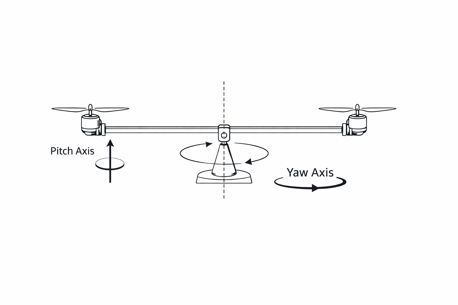
To control the twin rotor system, we must first understand its motion. The system is typically a beam pivoted on a base, allowing it to move freely in three degrees of freedom (DOF): pitch (vertical), elevation (horizontal) and travel (yaw). A DC motor with a propeller is mounted at each end of the beam.
- Pitch Axis: The main rotor generates a thrust force that causes the beam to pitch up or down. This is analogous to the main rotor of a helicopter providing lift.
- Travel Axis: The tail rotor produces a thrust force that causes the entire assembly to rotate horizontally around the central pivot. This mimics a helicopter's tail rotor, which counteracts the main rotor's torque and controls the craft's heading.
The core control problem arises from the pitch and travel control coupling. For instance, a sudden increase in main rotor speed to raise the pitch will also create a gyroscopic torque that affects the travel angle. Similarly, changes in the tail rotor's speed can introduce vibrations and slight changes in the beam's vertical position. A successful controller must anticipate and compensate for these interactions.
Mathematical Modeling
Developing an accurate mathematical model is the first step in designing a robust controller. The model captures the relationship between the inputs (motor voltages) and outputs (pitch and yaw angles). For the twin rotor system, this is often done using either transfer functions or a state space representation.
The state space approach is particularly powerful for MIMO systems as it provides a holistic view of the system's internal states. The standard state-space form is:
ẋ = Ax + Bu
y = Cx + Du
Where:
- x is the state vector (e.g., pitch angle, yaw angle, and their angular velocities)
- u is the input vector (left and right rotor thrusts)
- y is the output vector (pitch and yaw angles)
- A, B, C, and D are state-space matrices that define the system's dynamics.
Below is a simplified example of what the state-space matrices might look like in a twin rotor dynamics matlab implementation. The actual values would be derived from physical principles (like Newton-Euler equations) or identified through system identification experiments.
% Example State-Space Representation for a Twin Rotor MIMO System
% Note: These are illustrative values. Real parameters must be identified.

A = [0, 0, 1, 0;
     0, 0, 0, 1;
     -0.5, 0.1, -0.2, 0;
     0.1, -0.4, 0, -0.3];

B = [0, 0;
     0, 0;
     5, 0.1;
     0.2, 6];

C = [1, 0, 0, 0;
     0, 1, 0, 0];

D = [0, 0;
     0, 0];

sys = ss(A, B, C, D);
This model is fundamental for designing controllers like LQR or performing simulations to predict system behavior. The thrust force modeling of each rotor (often as a function of motor voltage and RPM) is a critical sub-component of this overall system model.
The 3-DoF Helicopter has an additional special purpose module called Thrust Measurement Module. It contains a modular cage and motor + propeller system, which is connected to a loadcell. The loadcell measures the linear force (thus thrust) that the motor + propeller generates. The motor’s electrical current is also monitored hence an input - output relationship between the electrical energy vs the mechanical energy can be obtained, as well as modelled using this part of the product.
Please watch our video below to learn more about the 3-DoF Helicopter’s different modules including the Thrust Measurement Module:
Control Design for Twin Rotor MIMO Systems
With a model in hand, we can design a controller. The goal is to manipulate the motor voltages to achieve desired pitch and yaw angles, rejecting disturbances and overcoming the inherent coupling.
PID Control
A common starting point is to use two separate Proportional-Integral-Derivative (PID) controllers—one for pitch and one for yaw. A PID controller helicopter strategy is simple to implement but has limitations. Because the PID controllers treat the system as two independent SISO loops, they can struggle with the strong coupling. Tuning can be difficult, as adjusting one loop often negatively impacts the other, leading to oscillations or sluggish performance.
State-Feedback Control (LQR)
Modern control techniques offer a more robust solution. The Linear-Quadratic Regulator (LQR) is a state-feedback method that is optimal by design. It uses the state-space model to calculate a feedback gain matrix, K, that minimizes a cost function based on state deviations and control effort.
The control law is u = -Kx. LQR naturally handles MIMO systems because the gain matrix K accounts for all interactions between the states. This results in better performance and stability compared to decoupled PID control.
To further enhance your understanding of State-Feedback control systems, we invite you to visit the blog post, "Automatic Control Example Series: A State Feedback Controller Using Ball Balancing Table."
Explore the 3-DoF Copter — Acrome's lab-ready twin rotor MIMO experiment system designed for hands-on learning and research.
Experiment Design for the Lab
Translating theory into a successful MIMO control system experiment requires careful planning. Here is a typical workflow for a twin rotor MIMO system control experiments session:
- System Identification: First, perform experiments to find the parameters for your mathematical model. This can involve applying step inputs to each rotor and measuring the system's response to identify parameters like damping and thrust coefficients.
- Controller Design & Simulation: Use the identified model to design your controller (e.g., tune PID gains or calculate the LQR gain matrix K) in a simulation environment like MATLAB/Simulink. Verify that the controller is stable and meets performance requirements in simulation first.
- Real-Time Implementation: Deploy the controller onto the real hardware. Start with small setpoint changes to ensure the system is stable. Test its ability to track setpoints for both pitch and yaw simultaneously.
- Performance Analysis: Evaluate the controller's performance by measuring metrics like rise time, settling time, overshoot, and its ability to reject disturbances (e.g., by gently pushing the beam).
Applications and Research Directions
The study of multi-input multi-output systems like the twin rotor platform is not just an academic exercise. The principles are directly applicable to a wide range of real-world systems, including:
- Aerospace: Controlling drones, helicopters, and fixed-wing aircraft.
- Robotics: Coordinating the motion of multi-axis robotic arms.
- Process Control: Managing temperature and pressure in chemical reactors.
- Automotive: Vehicle stability control systems that manage braking and steering.
Ongoing research continues to push the boundaries, exploring nonlinear control techniques, adaptive controllers that can adjust to changing system dynamics, and fault-tolerant control to handle sensor or actuator failures. The twin rotor system remains a valuable and accessible platform for exploring these advanced topics.
Conclusion
The twin rotor MIMO system provides an excellent bridge from single-loop control theory to the more complex, coupled world of multi-variable systems. We've seen how its dynamics are defined by the interaction between pitch and yaw, necessitating a mathematical model—preferably a state space representation—for effective control design. While PID offers a simple starting point, modern methods like LQR deliver far superior performance by treating the system holistically. By following a structured experiment design process, from modeling and simulation to real-time implementation, engineers and students can gain invaluable hands-on experience. The insights gained from mastering a twin rotor MIMO system are directly transferable to countless advanced engineering challenges.
Frequently Asked Questions (FAQ)
1. What is the main difference between a SISO and a MIMO system?A SISO (Single-Input Single-Output) system has one input controlling one output. A MIMO (Multi-Input Multi-Output) system has multiple inputs affecting multiple outputs, often with coupling between them, making control more complex.
2. Why is a twin rotor system considered a MIMO system?It has two inputs (main and tail rotor voltages) and two outputs (pitch and yaw angles). The key is that the inputs are coupled—changing the main rotor speed affects both pitch and yaw, and vice versa.
3. What is state-space representation and why is it useful for MIMO systems?State-space representation is a mathematical model that describes a system using a set of first-order differential equations. It is ideal for MIMO systems because it provides a comprehensive view of all internal states and their interactions, which is essential for advanced control techniques like LQR.
4. Can I use PID to control a twin rotor system?Yes, you can use two separate PID controllers, but their performance will be limited due to the coupling between the pitch and yaw axes. Tuning them can be challenging, and they may not provide the stability and responsiveness of a true MIMO controller like LQR.
5. What is LQR control?LQR (Linear-Quadratic Regulator) is an optimal control method that uses the system's state-space model to calculate a feedback gain matrix. It is highly effective for MIMO systems because it systematically accounts for all couplings, leading to robust and high-performance control.
Author
